36
|
CERECDOCTORS.COM
|
QUARTER 2
|
2015
An alginate impression was obtained and a CEREC Guide
radiographic scanning appliance was fabricated indirectly incor-
porating the appropriately sized CEREC Guide reference body.
This CEREC Guide scanning appliance was then placed in the
patient’s mouth and a cone beam CT radiographic evaluation was
performed with the Sirona Orthophos XG3D CBCT machine.
In addition, a digital impression of the patient’s maxillary arch
was obtained via scanning with the CEREC Omnicam and a virtual
restoration was designed in the CEREC Chairside software, which
was exported as CAD/CAM data into the Galileos Implant treat-
ment planning software where it was merged with the CBCT
scan. The Galileos Implant treatment planning software was
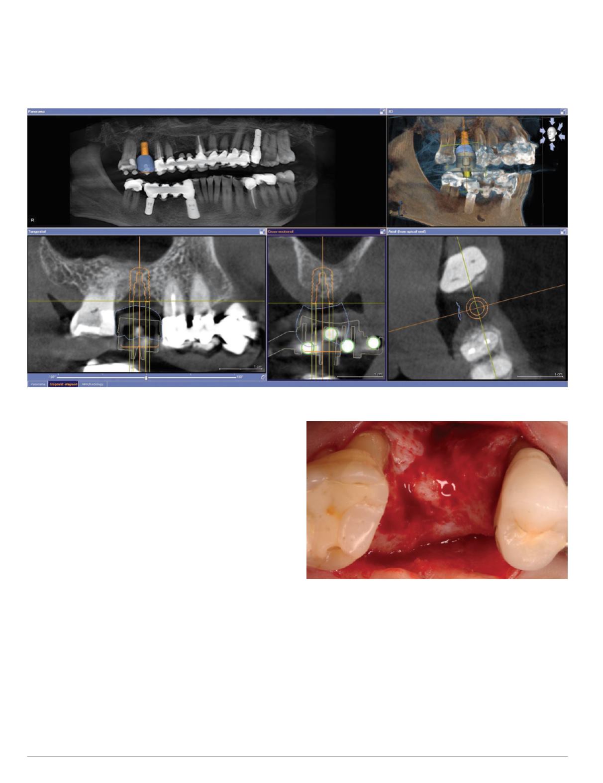
utilized to plan a Straumann bone level implant in site #3 (Fig. 9).
The key in treatment planning the implant position is to virtually place
the implant slightly short of the maxillary sinus floor (Fig. 9). The
treatment planning data was exported from the Galileos Implant
software and imported back into the CEREC Chairside software to
mill the corresponding CEREC Guide drill body. The CEREC Guide
reference body was replaced with this milled drill body, thereby
converting theCERECGuide scanning appliance into a surgical guide.
The second surgical procedurewas performed under local anes-
thesia and intravenous conscious sedation, and venous blood was
again collected to obtain a Platelet Rich Fibrin (PRF) concentrate
| | |
B O LT C H I
via a centrifuge system. A full-thickness bucco-lingual mucoperi-
osteal flapwas elevated in sites #2-4without any vertical releasing
incisions. This revealed a moderate buccal and a mild palatal
alveolar ridge deficiency (Fig. 10).
The CEREC Guide, the Sirona CEREC Guide keys for the
Straumann system, and the Straumann Guided Surgery drills were
then utilized to prepare the guided implant osteotomy up to the
3.5mmdrilldiameterjustshortofthemaxillarysinusflooraccording
to the virtual treatment plan in the Galileos Implant software.
Fig. 9: CBCT implant treatment plan for site #3
Fig. 10: Occlusal view site #3 after flap reflection


