23
to start developing the implant tissue transition zone, a decision
was made to provide the patient with an immediate, non-functional
provisional restoration. The peri-implant bone and soft tissueswere
adjusted using the Straumann Guided Bone Profiling System. A
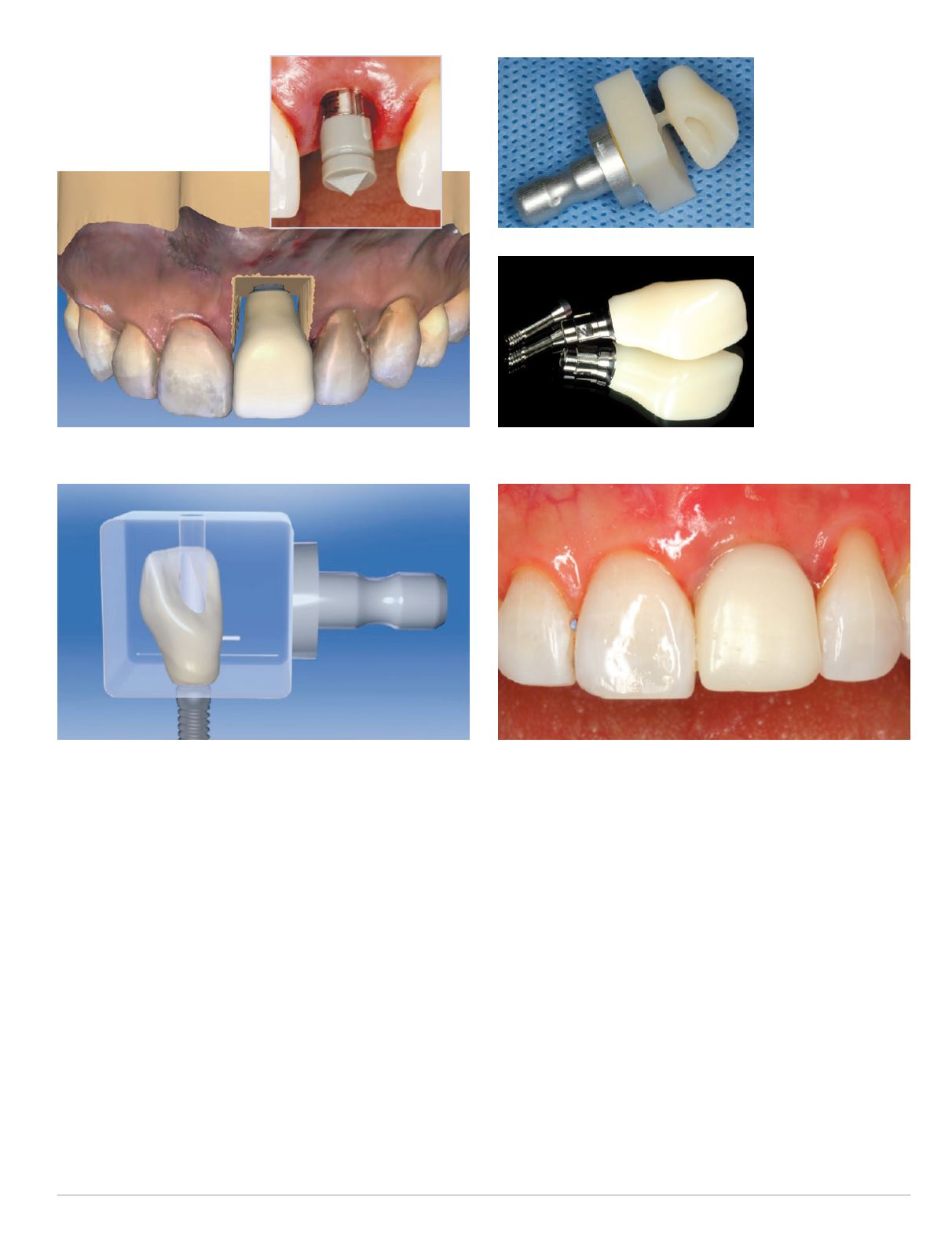
Sirona ScanPost for the Straumann Bone Level RC implant with the
corresponding ScanBody was inserted onto the implant (Figure 15),
a CEREC Omnicam digital impression/scan of the ScanBody was
obtained and a custom screw-retained provisional restoration was
designed in the CEREC software (Figs. 16-17).
The corresponding restoration was then milled out of an Ivoclar
Telio CAD Implant Solutions A16 block, adjusted and polished, and
then bonded to a Straumann RC Bone Level Variobase for CEREC
with the Ivoclar Multilink Hybrid Abutment Cement (Figs. 18-19).
This provisional restoration was taken completely out of occlu-
sion in all centric and excursive movements, and screwed onto the
implant todevelop the ideal peri-implant soft tissue profile (Fig. 20).
Fig. 15 (right): ScanPost and
ScanBody in place
The immediate post-operative periapical and cone beam CT radio-
graphic evaluation confirmed the placement of the implant in
accordance with the pre-operative virtual implant treatment plan
(Figs. 21-22).
After an uneventful healing period of six weeks, the previous
digital full-contour design in the CEREC software was split
to design a custom hybrid abutment and the corresponding
cementable crown. This design was then used to mill an e.max
customhybrid abutment out of an Ivoclar e.maxHybrid Abutment
A14 Block, along with a new cementable Telio CAD provisional
crown. The custom hybrid abutment was then once again bonded
to a Straumann RC Bone Level Variobase for CEREC with the
Ivoclar Multilink Hybrid Abutment Cement (Fig. 23).
The screw-retained provisional restoration was then removed,
revealing an ideally contoured peri-implant soft tissue transition
zone (Figs. 24-25). The screw-retained custom hybrid abutment
Fig. 16: Restorative design in CEREC software 4.4
Fig. 17: Mill preview of the screw-retained provisional crown
Fig. 18 (left):
Milled Telio CAD
provisional crown
Fig. 19 (left):
Milled provisional
crown bonded
to Straumann
Variobase for
CEREC
Fig. 20: Screw-retained immediate provisional restoration inserted
onto implant


