41
• Do the teeth have proper proportions (height-to-width ratios)?
• What material would satisfy the patient’s expectations and
work functionally long term?
In this case, the incisal edge was in the correct position, the
midline was correct, the proportions and symmetry were very
close (only had to re-contour the composite on the distal of #9),
and the material chosen was going to be feldspathic porcelain.
(None: We are not going to discuss materials in this article. An
article was published in the Q2 2014 issue of
cerecdoctors.com
magazine discussing this topic.)
Because we satisfied the above questions with the existing
restorations, we can do this case with straight Biogeneric Copy. If
that was not the case, we would have to do an intraoral mock-up
with resin or create a diagnostic wax-up.
After imaging the existing restorations for our Biogeneric Copy
and preparing the teeth for three-quarter crowns (Figs. 2 and 3),
we can begin the design process. Because we want to copy the
existing restorations exactly, care must be taken to draw the white
copy line around the entirety of both restorations (Fig. 4). (Note:
You cannot draw both copy lines at the same time. This image was
a merging of two copy line images).
The initial proposals generated by the software will be exact
replicas of the existing teeth and mimic the incisal length, midline
and symmetry we are trying to recreate (Fig. 5). Once we have
achieved symmetry through Biogeneric Copy, the goal from this
point forward in the design process is never to lose it.
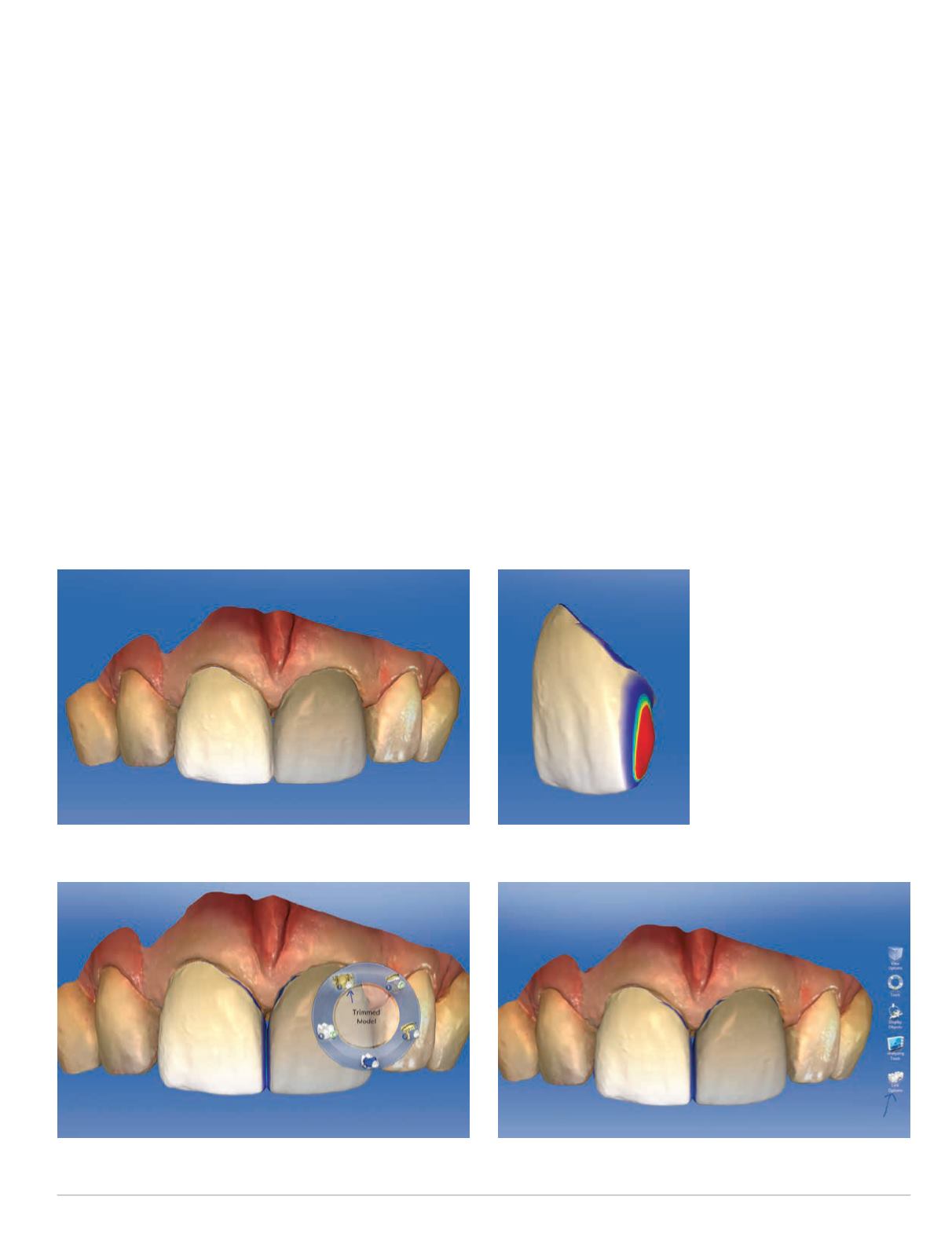
One of the issues the software has with Biogeneric Copy is that
it creates very heavy midline contacts (red). This is a problem
because in order to maintain perfect symmetry, the heavy contacts
must be adjusted symmetrically. If you check the contacts via
“Trimmed Model” (Fig. 6) (Note: You can activate the Display
Objects Tool Wheel by depressing the “D” key on the keyboard).
You can see the penetrating red interproximal contact (Fig. 7).
Fig. 5: Initial proposals
Fig. 6: Using “TrimmedModel” shortcut
Fig. 7: Red interproximal contact
Fig. 8: Activating link options


