42
|
CERECDOCTORS.COM
|
QUARTER 1
|
2016
C A S E S T U D Y
| | |
B Y M I K E S K R A M S TA D , D . D . S .
the release of cerec sw v4.4 has brought many wonderful new features
to our already great chairside software.
The introduction of a CEREC Guide 2, a new, efficient interface, includes better margination, more accurate milling of margins
and better proposals to name just a few features. In this article, I would like to concentrate on the proposals. Specifically, how
we can take advantage of the new Biojaw algorithmwith anterior teeth to get excellent, quick and efficient proposals.
Anterior Biojaw Magic With V4.4
How to Get Quick and Efficient Proposals for Anterior Teeth
CASE STUDY
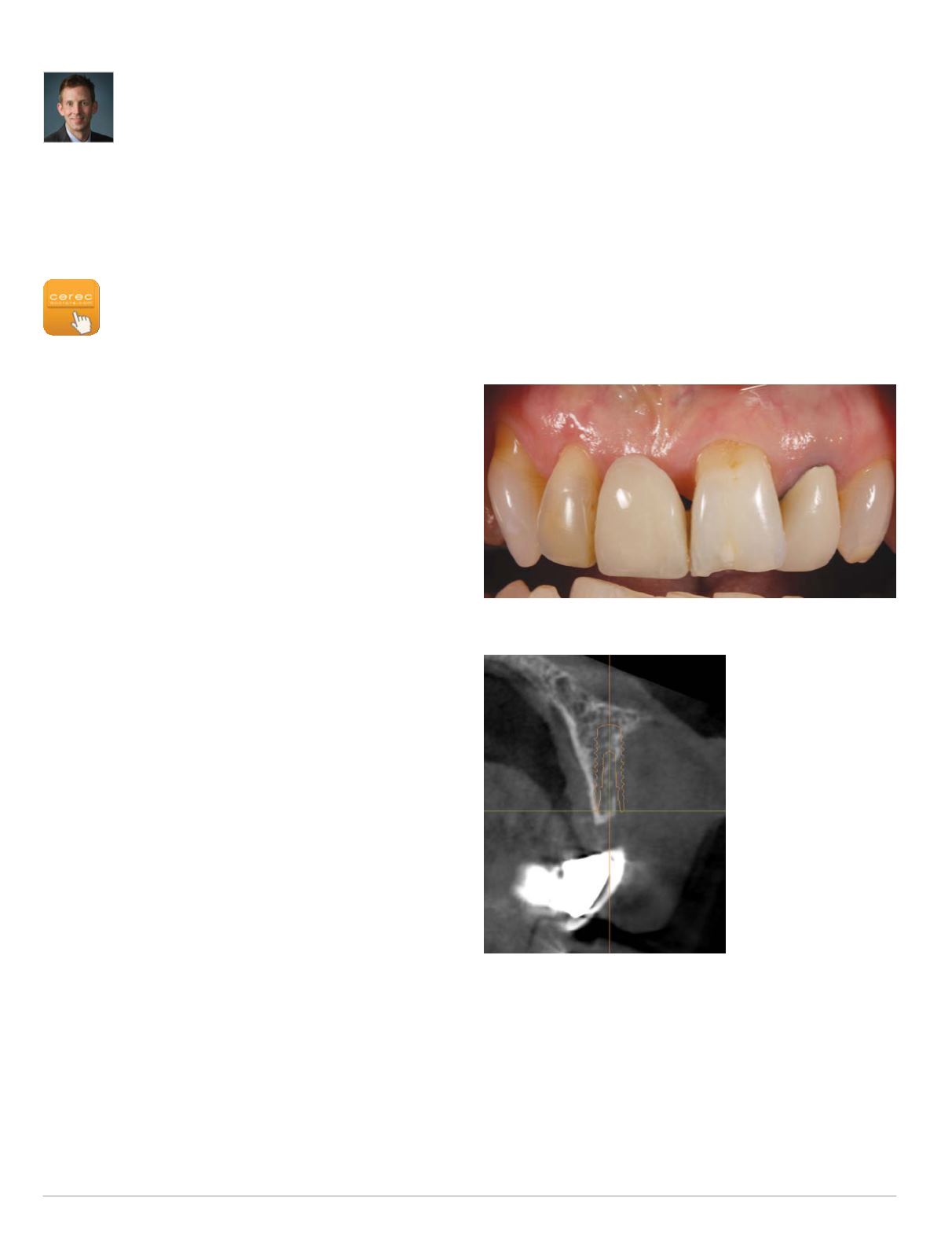
The patient presented with a missing tooth #8 and a Maryland
Bridge replacing this tooth with two metal wings on the lingual of
#7 and#9. She alsohad aRCTandPFMcrownon tooth#10 (Fig. 1).
Her initial concerns included:
• She did not like the “black” spacing around the pontic
• She noticed there was a “grey hue” showing through tooth #7
and #9 from the metal wings
• She had fractured the incisal of #9 in an accident, and wanted
that repaired
• She did not like the older PFM on #10 esthetically
• She wanted a better overall shape to her front four teeth
In looking at her options, we discussed a few different ideas.
The first option was implant placement to replace the missing #8.
We took a 3-D cone beam scan (Sirona XG3D), and planned an
implant placement with a 3.3 Straumann NC bone level implant
(Sirona Galaxis software). Because the tooth was missing for so
many years, the ridge had resorbed substantially, meaning implant
placement without extensive grafting was not an option (Fig. 2).
We also considered orthodontics to level out her gingival zeniths
before final treatment, but this was deferred due to added cost,
time and the fact that a low lip line hid this esthetic problem.
Our final treatment plan consisted of a conventional bridge
from #7 to #9 and a new crown on tooth #10. The hope was to
upright her teeth just a little bit, create a little more freeway space,
and create a more harmonic, symmetric arch form fromwhere she
was at the beginning of treatment (Fig. 3).
After imaging theBiocopy arch for reference later, the teethwere
prepared for full-coverage crowns (Fig. 4). Reduction on #7 and
#9 was done using Dr. Bob Winters Restorative Design reduction
burs to make sure ideas reduction was achieved. When removing
the PFM on #10, the preparation had a very dark shade. When
considering materials, there were two things that were going to
help with this issue. First, we had to commit to e.max CAD LT
because of the anterior bridge (want all materials to be the same
translucency). Second, tooth #10 needed to be moved facially to
create the harmonic arch. The increased thickness of the material
should help block out the dark shade of the preparation.
After imaging the case in the software and margination, we got
the initial proposal (Fig. 5). The proposal was not ideal and would
have taken quite some time to reworkwith the tools. Here is where
SW v4.4 has a huge advantage. We can click on the “Bio Jaw”
icon in the lower left corner of the screen to quickly create an
Fig. 1: Pre-op condition
Fig. 2: 3-D cone beam
scan #8 area


